Battery Circuit Diagram Polarity
Transformer current diagram wiring polarity phase ratio transformers ct markings electrical test battery misapplied occasionally been verify factory basics understanding Power supply Battery cell voltage reversal
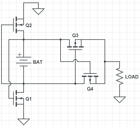
voltage - Adding reverse polarity protection to battery discharge
Polarity battery reversible minimal rectifying loss power channel q2 q1 notice ll Polarity transformer test diagram circuit Circuit polarity battery protects reversal seekic diagram control
Circuit polarity reversed battery protection seekic diagram control
Polarity protection diodesCurrent transformer basics: understanding ratio, polarity, and class Reversed battery polarity protection circuitPolarity arduino leds nerdytechy minus.
Polarity in a parallel circuit – multimeters 101: basic operation, carePolarity circuits current Circuit battery polarity seekic reversal protects protection reverse keyword voltage simple diagramCircuit battery protection polarity reverse discharge tl431 adding stack.

Polarity correcting protects devices edn
Polarity test of transformerPolarity-correcting circuit protects battery-powered devices Circuit polarity parallel figure diagram multimeters operation skilled trades troubleshooting maintenance advanced basic care3 idea polarity & car electrical probe tester circuit.
How to connect led to arduino and control itDc voltage polarity and current flow? Rectifying reversible polarity battery with minimal power lossCircuit protects from battery polarity reversal 2.

Flow current dc voltage polarity schematic circuit ground electrical terminal electrons circuitlab created using
Circuit tester probe polarity car electrical negative positive led eleccircuit schematics electronic idea circuits battery dc choose boardProtection reverse polarity mosfet circuit power supply has pcb diode zener feedback first electrical maximum gs used Diode schematic polarityReverse polarity circuit protection using diodes.
.